The customer needed a cabinet product consisting of 3 inverters and to achieve its purpose of use
Design requirements
- The protection level of the cabinet is IP20.
- Cabinet wiring: all secondary voltage lines in the cabinet are BVR-0.75mm2 or 1.0 mm2 multi-stranded copper wire, current transformer lead wires using voltage 750V, 2.5mm2 multi-stranded copper wire.
- All secondary components and control circuit external wiring are accessed through the terminal block or lead out. There are spare terminals in the terminal block. According to the EMC rules of wiring, strong and weak power cables are separated to prevent the inverter from interfering with other equipment and the power grid.
- The components in the cabinet are arranged with reasonable intervals, giving full consideration to the convenience of disassembling and assembling components and maintenance.
- The cabinet has good insulation, and the insulation of the device and the cabinet is above 5M ohms;
- The inverter cabinet’s inlet and outlet are under the inlet and outlet.
- There is an ammeter and voltmeter on the front door panel of the cabinet. Each cabinet door has a Chinese nameplate made of stainless steel plate, and the content of the nameplate is in line with the relevant standards.
- There is a wiring diagram of the unit circuit on the inside of the door of each cabinet.
According to customer requirements, this system adopts one tow one control.
Cabinet configuration: frequency converter, secondary control components.
Cabinet door configuration: voltmeter, ammeter, local/remote two knob switch (spare), inverter run button, inverter stop button, inverter run indication, inverter fault indication, inverter operation keyboard introduced into the cabinet door.
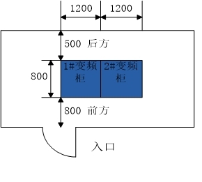
Cabinet installation diagram:

Item Name Specification
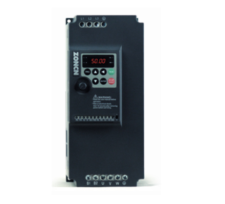
Series NZ200 Series General Purpose Vector Inverter
Basic functions Control mode V/F control
Open-loop vector control (no PG)
Maximum frequency Vector control: 0-320Hz
V/F control: 0~3200Hz
Carrier frequency 1kHz~16kHz
Carrier frequency can be adjusted automatically according to the load characteristics.
Input frequency resolution Digital setting: 0.01Hz
Analogue setting: Maximum frequency × 0.025%
Starting torque G-type machine: 0.5Hz/150% (without PG);.
P-type machine: 0.5Hz/100%
Speed range 1:100 (without PG)
Accuracy of speed regulation ±0.5% (without PG)
Overload capacity G-type machine: 150% rated current 60s; 180% rated current 3s.
P-type machine: 120% rated current 60s;150% rated current 3s.
Torque boost Automatic torque boost; manual torque boost 0.1%~30.0
V/F curve Three ways: Linear; Multi-point; N-square V/F curve (1.2-square, 1.4-square, 1.6-square, 1.8-square, 2-square)
V/F separation 2 types: full separation, half separation
Acceleration and deceleration curves Linear or S-curve acceleration and deceleration methods. Four kinds of acceleration and deceleration time, acceleration and deceleration time range 0.0~6500.0s
DC braking DC braking frequency: 0.00Hz~maximum frequency; braking time: 0.0s~100.0s; braking action current value: 0.0%~100.0%
Tap control Tap frequency range: 0.00Hz~50.00Hz; tap acceleration/deceleration time 0.0s~6500.0s.
Simple PLC,
Multi-Segment Speed Operation Up to 16 segments speed operation by built-in PLC or control terminal.
Built-in PID for easy realisation of closed-loop process control system.
Automatic Voltage Regulation (AVR)
(AVR) Automatically maintains a constant output voltage when the grid voltage varies.
Over-voltage and over-voltage speed control Automatic limitation of current and voltage during operation to prevent frequent over-current and over-voltage trips.
Fast current limiting function Minimises overcurrent faults and protects the normal operation of the inverter.
Torque limiting and control “digger” characteristics, automatic limitation of torque during operation, to prevent frequent overcurrent tripping
High-performance asynchronous motor control with high-performance current vector control.
Instantaneous stopping and non-stopping Compensates for the voltage drop during an instantaneous power failure by feeding energy back from the load, and maintains the inverter in operation for a short period of time.
Fast current limitation Avoids frequent overcurrent faults of the inverter.
Timing control Timing control function: Setting time range 0.0Min~6500.0Min.
Communication mode support RS-485
Run Run command channel Keyboard setting, control terminal setting, serial communication port setting. Can be switched by various ways
Frequency sources 10 kinds of frequency sources: digital give, analogue voltage give, analogue current give, pulse give, serial port give. Can be switched in various ways
Switchable in various ways
Auxiliary frequency sources 10 auxiliary frequency sources. Auxiliary frequency fine-tuning and frequency synthesis can be flexibly realised.
Input terminals Standard:
6 digital input terminals, 1 of which supports high-speed pulse input up to 100kHz (S3 optional); 2 analogue input terminals, 1 of which supports only 0 to 10V voltage input (S3 optional).
Two analogue input terminals, one supporting only 0-10V voltage input (FIV), one supporting 0-10V voltage input or 4-20mA current input (FIC).
Input (FIC)
Output terminal 1 digital output terminal (MO1)
1 relay output terminal (RA, RB, RC)
1 analogue output terminal supporting 0-20mA current output or 0-10V voltage output (FOV)
Remarks X terminal is NPN type by default, if you need PNP type, you need to customise it.
Display and Function
Keypad operation LED display Parameter display
Key lock and Function Selection
Partial or full locking of keys and definition of the function range of some keys to prevent misoperation.
Protection functions Motor short circuit detection, output phase loss protection, over-current protection, over-voltage protection, under-voltage protection, over-heat protection, overload protection, etc.
Environment Indoor, no direct sunlight, no dust, corrosive gases, flammable gases, oil mist, water vapour, dripping water or salt, etc.
Altitude Less than 1000m (higher than 1,000 metres need to be downgraded to use)
Ambient temperature -10℃~+40℃
(Ambient temperature in 40 ℃ ~ 50 ℃, please downgrade use)
Humidity Less than 95%RH, no water condensation.
Vibration Less than 5.9m/s²(0.6g)
Storage temperature -20℃~+60℃
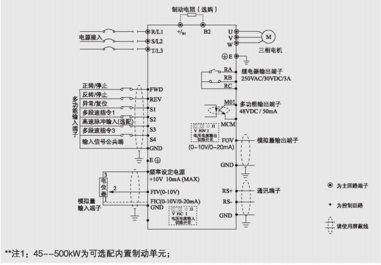
Basic Wiring Diagram of Inverter 45-630KW

NZ200 frequency converter is more popular and run efficiently and stably a frequency converter, this programme, according to the guests need to request, customize the parameters and details of the frequency converter cabinet, in order to achieve the desired function, ZONCN has been following the guests’ requirements, to provide the best frequency converter programme. Any questions, please feel free to contact us.

