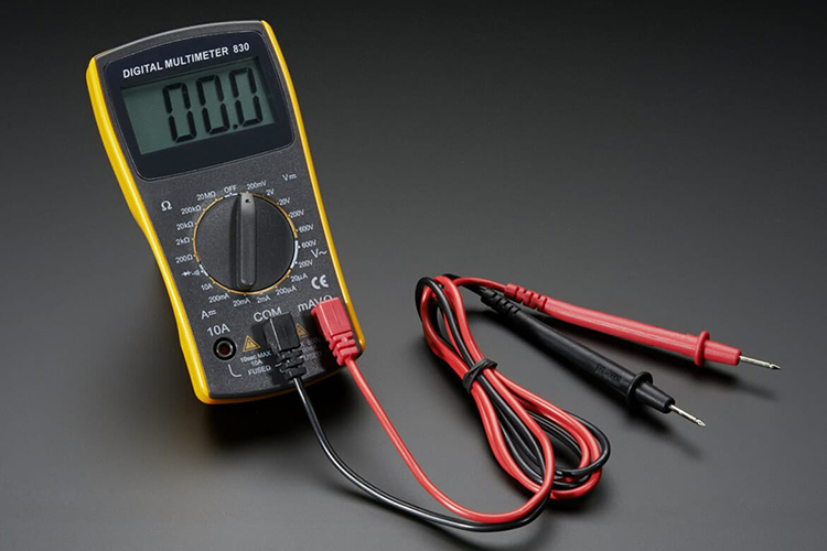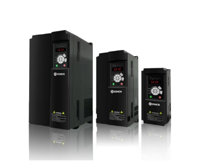
As inverters are used more and more frequently in daily life, we need to know more about inverters, and using a multimeter to detect the good and bad inverters is a common method.
First of all, make sure that the inverter has been properly connected to the power supply and is in the on state. Use a multimeter to measure whether the input of the inverter has the correct voltage output. This will confirm that the inverter is receiving the power supply properly. Then, measure the output port of the inverter, usually where the motor is wired. Measure the voltage and frequency at the output port with a multimeter. During normal operation of the inverter, the output should have a stable voltage and frequency.
If the inverter has troubleshooting capabilities, a multimeter can be used to check for any fault codes. Connect the multimeter to the appropriate port according to the model number of the inverter and the manufacturer’s guidelines, and check the status of the fault codes or fault indicators.
Specific operations are as follows:
1, find the inverter internal DC power supply P (+) end and N (-) end, the multimeter will be adjusted to the diode file black pen on the inverter P (+), the red pen were measured in turn R, S, T three-phase numbers are the same and basically balanced, indicating that the inverter is good, such as measured values are not the same as that of the inverter module damage.
2, to find the inverter internal DC power supply P (+) terminal and N (-) terminal, the multimeter will be adjusted to the diode file red pen on the inverter N (-), black pen were measured in turn U, V, W three-phase numbers are the same and basically balanced, indicating that the inverter is good, such as measured values are not the same that the inverter module is damaged.
Notes.
1, In the detection of inverter module good or bad, remove the inverter R, S, T terminals U, V, W terminals automatic resistance.
2, With the same method can measure a variety of inverter good or bad.
3, Such as inverter reported over-voltage, under-voltage when checking whether the inverter module is damaged, with the above method to measure the inverter good or bad.
4, There are times when the total switch may be jumped inverter module damage, first do not rush on the power, with the above method to measure the inverter good or bad.
Measurement of DC bus voltage
1, The purpose of measurement: when the inverter reported phase loss, undervoltage, measurement of the input voltage and no problem, measurement of this voltage, used to determine which circuit inside the inverter is a problem.
2, Measuring instrument: DC voltmeter, choose 1000V DC block.
3, The measurement method: the red pen connected to the DC bus P point (with the corresponding terminals), the black pen connected to the N point, read out the measured voltage value. According to the rectification principle, the inverter should be measured under load. Only when measured under load, can we see whether the voltage is low. The voltage under load is lower than 470V, the capacity of the filter capacitor decreases, and lower than 400V, the phase is missing.
Finally, compare with the inverter’s specifications or normal operating parameters. Check that the measured voltage, frequency and control signals match the specifications of the inverter. Please note that before performing these steps, be sure to consult the inverter’s instruction manual for proper test methods and safety precautions. Also, make sure that you disconnect the inverter from the power supply and take the necessary safety measures before performing any measurements.

