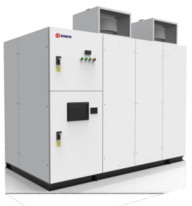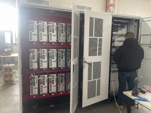
The high-voltage inverter has a highly intelligent computing level and a complete fault detection circuit, and can provide precise positioning of all faults and give clear instructions on the main control interface. In actual applications, we found that common faults can be divided into control channel abnormalities, IGBT overcurrent, overvoltage faults, etc. Here we analyze common high-voltage inverter faults, their causes, and methods for repairing high-voltage inverters.
1. Abnormal failure of control channel
Abnormal control channel faults are usually caused by the optical fiber communication between the sub-PWM board and the power unit board, generally due to the following situations:
- 1. The optical fiber connection part has poor contact or the optical fiber head falls off;
- 2. Dust accumulates inside the optical fiber signal transmitter/receiver;
- 3. The optical fiber is broken;
- 4. Optical fiber communication control vibration is damaged;
In the event of an optical fiber failure, you first need to determine whether it is a power unit failure or a fault on the controller side. This can be determined by swapping optical fibers. Swap the optical fiber corresponding to any power unit of the same phase on the optical fiber board in the controller with the fiber that reported the fault. After powering on again, if the optical fiber fault located on the monitoring interface is still in the original position, it means that the optical fiber board is damaged, otherwise , if the optical fiber fault displayed on the monitoring interface has been replaced, it means that the power unit is faulty. At this time, you can consider replacing or repairing the faulty power unit.

2. Causes and solutions of IGBT overcurrent faults
IGBT is the most critical power device in high-voltage inverters. As a high-power composite device, IGBT has the problem that locking may occur during overcurrent and cause damage. In order to improve the reliability of system charging, some measures have been taken to prevent damage due to overcurrent. The usual causes of IGBT overcurrent faults are as follows:
- 1. The inverter output is short-circuited;
- 2. The IGBT in the power unit is broken down;
- 3. The drive detection circuit is damaged
- 4. The detection circuit is interfered with;
The detection method is to find the corresponding module based on the fault location displayed on the monitoring interface, disassemble it and check whether the IGBT is damaged. The method of judgment is to find the positive v+ and negative v- of the DC bus inside the power unit. Connect the black meter of the multimeter to v+, and the red meter pens to U and V respectively. Use the diode mode, and it should display a value of about 0.4V. If it is reversed, it will display infinity. Connect the red test lead to v1 and repeat the above steps. The same result should be obtained. Otherwise, it can be judged that the IGBT is damaged and needs to be replaced.
3. Causes and solutions of overvoltage faults
The cause of overvoltage is generally overvoltage from the input side of the power supply. Under normal circumstances, the grid voltage is within -10%~+10% of the rated voltage, but under special circumstances. Since the DC bus voltage rises with the power supply voltage, when the voltage rises to the protection value, the inverter will trip due to overvoltage protection. In order to avoid overvoltage on the input side, the tap of the transformer can be changed for adjustment. If necessary, use voltage stabilizing equipment and check the braking resistor and braking unit at the same time.
